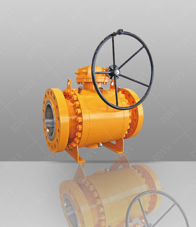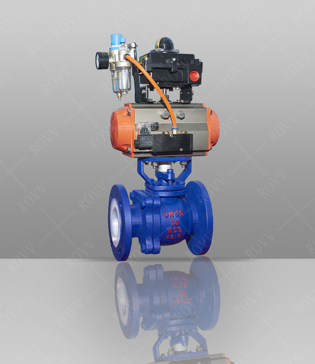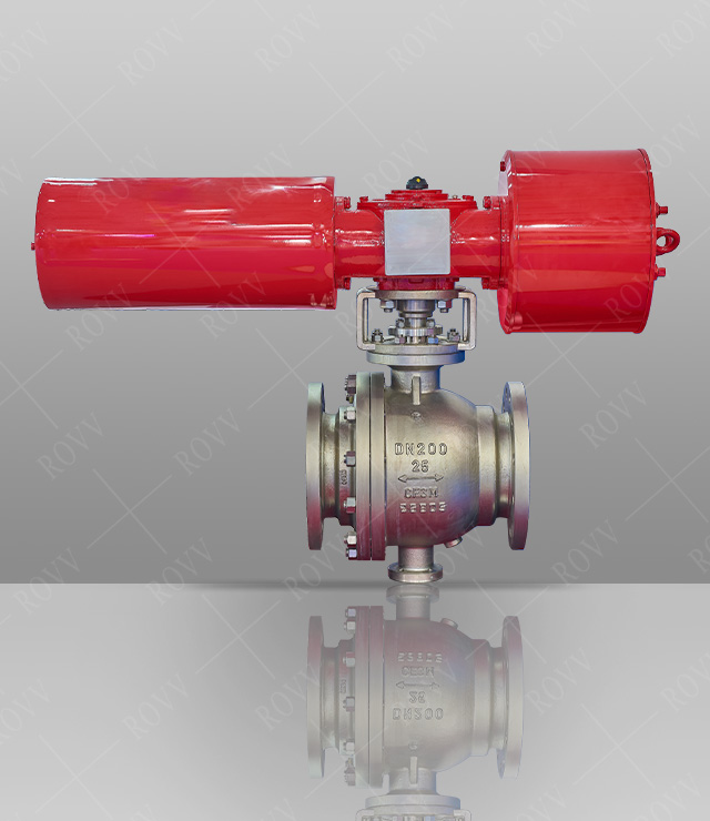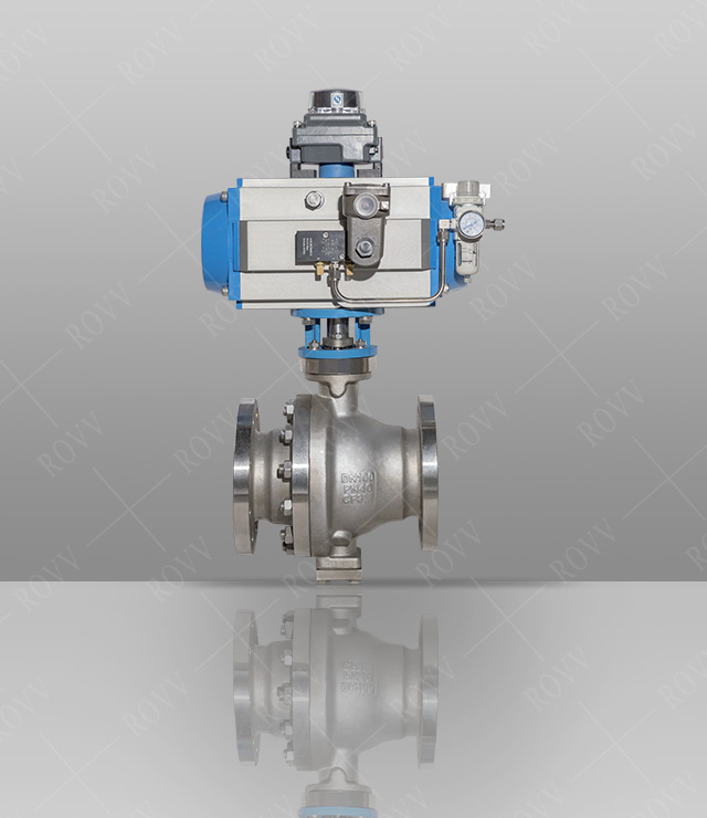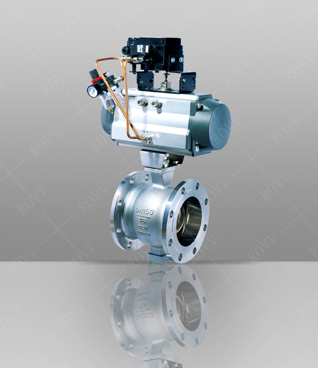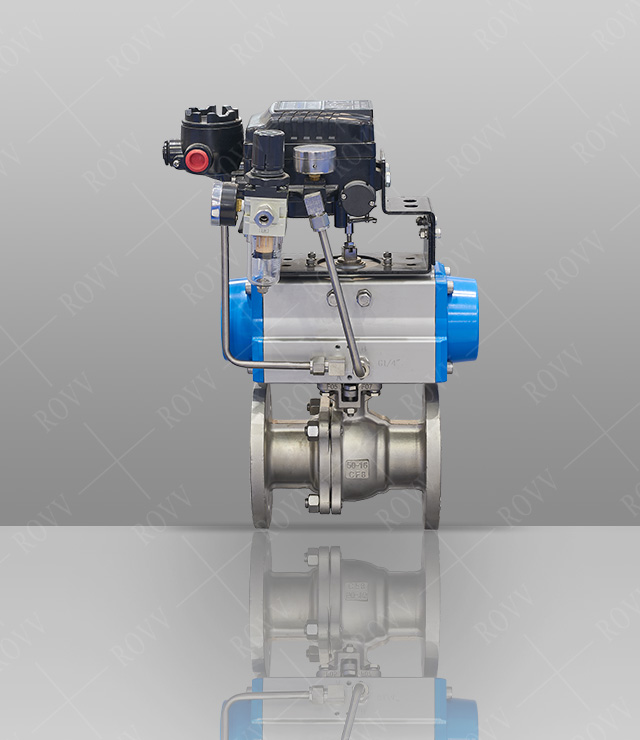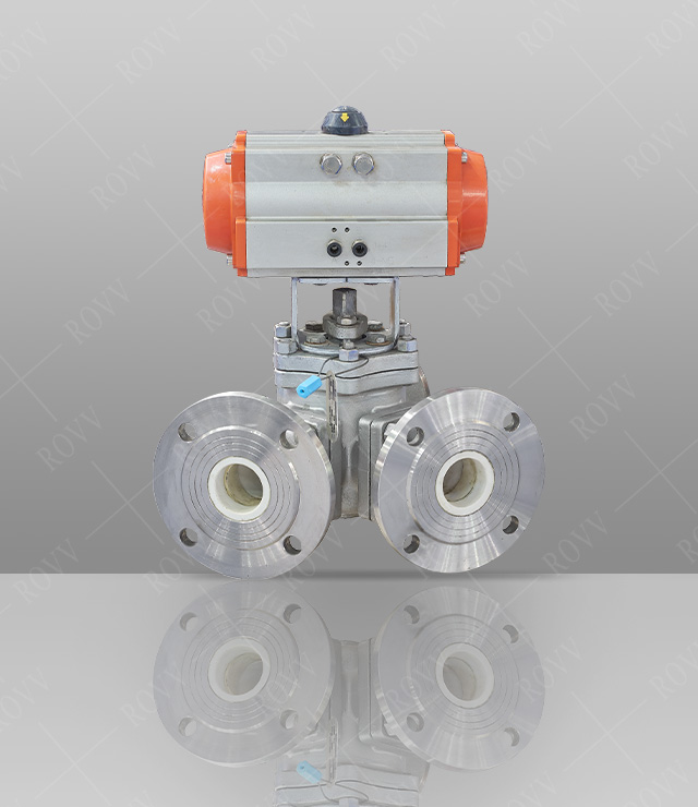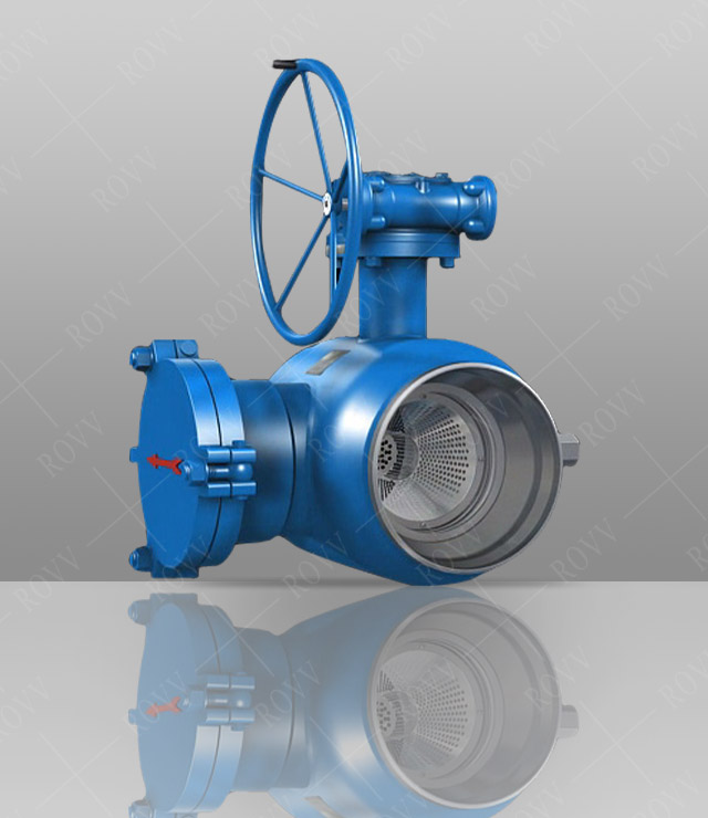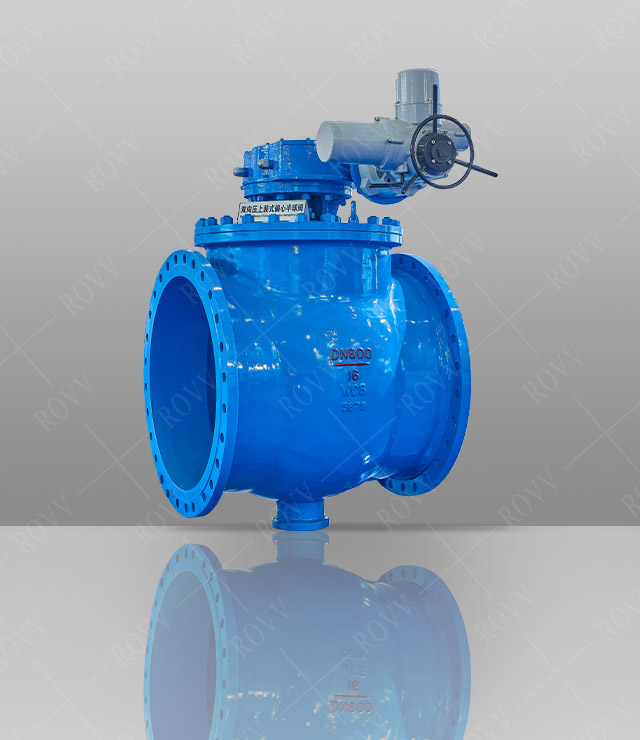
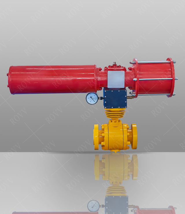
Forged Steel Trunnion Type Ball Valve(Pneumatic )
Technical Parameters
Product model: Q647F/H/Y-16C
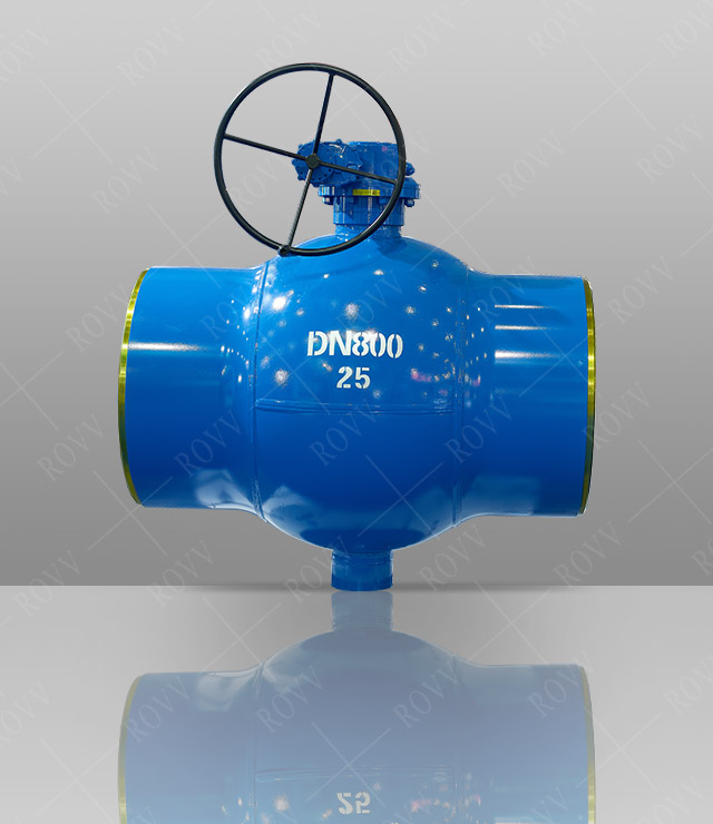
Nominal diameter: DN50-500mm
Working pressure: PN1.0-42.0MPa
Working temperature: -29~+450℃.
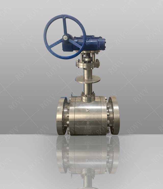
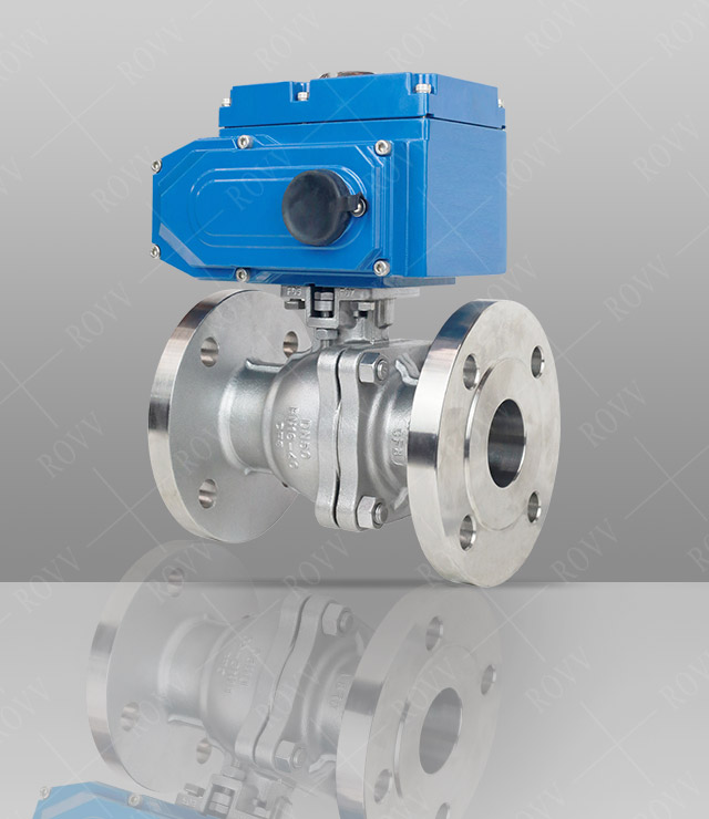
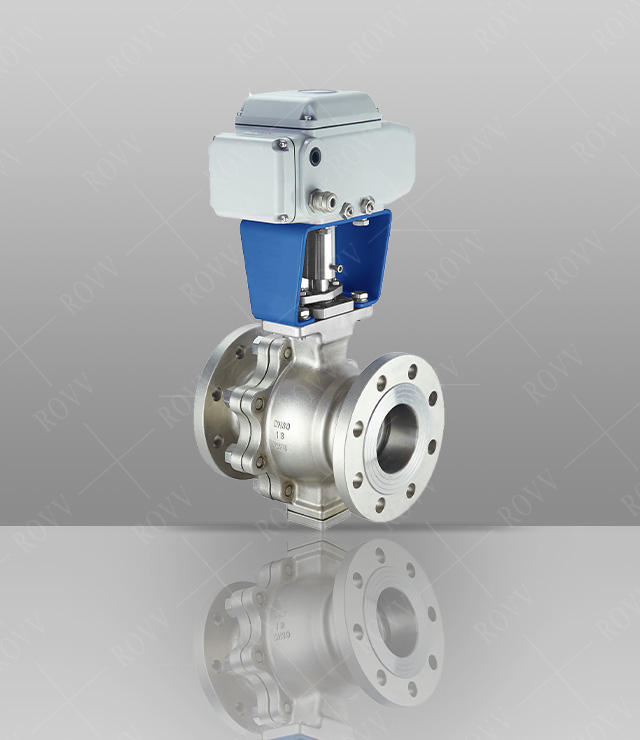
Drive mode: pneumatic
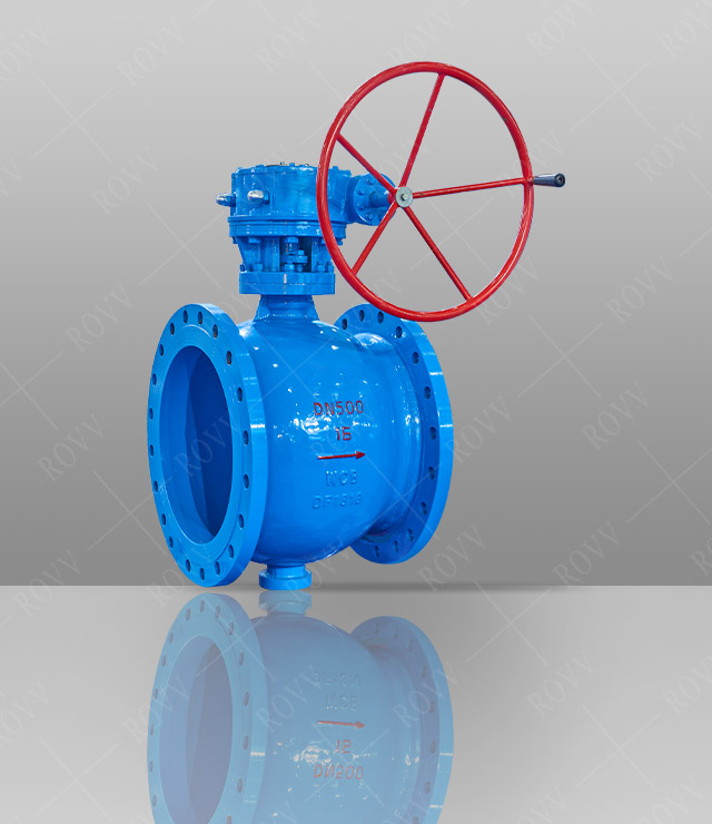
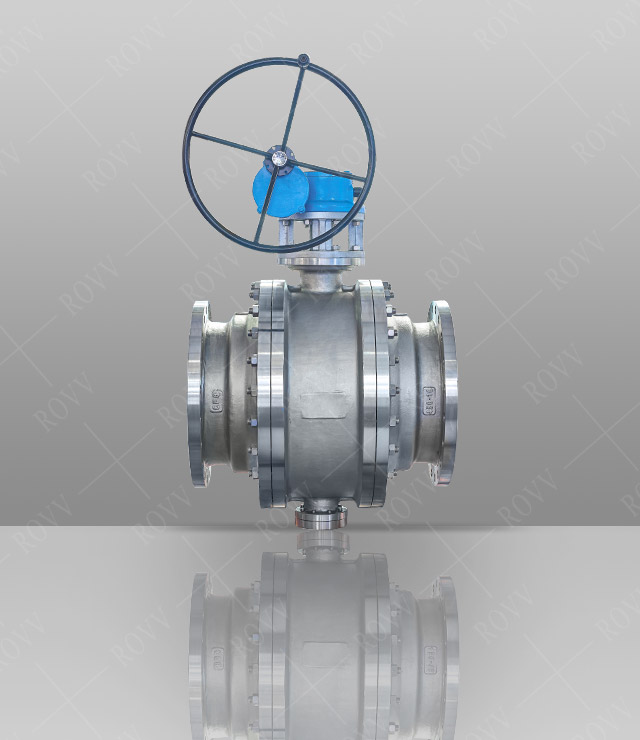
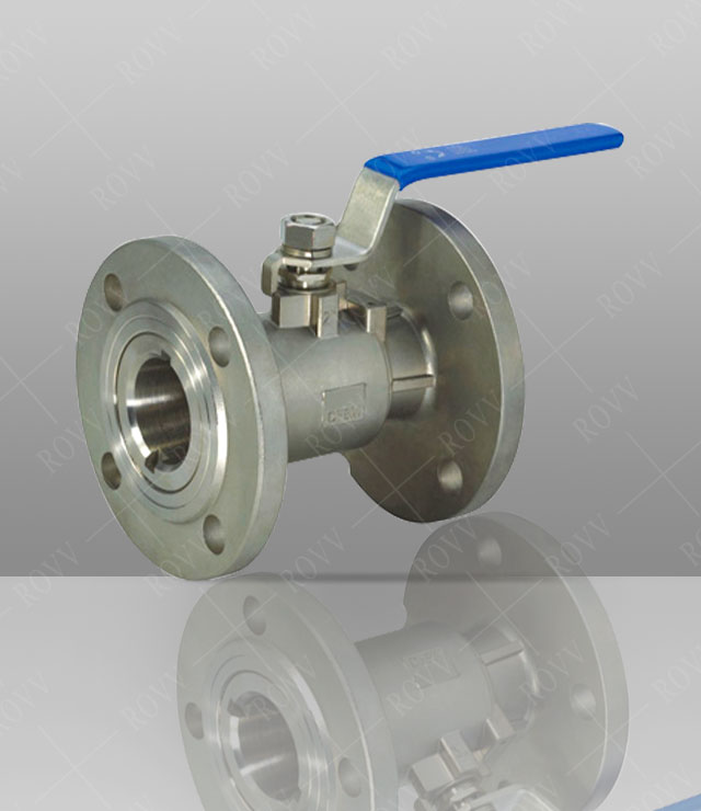
Connection method: flange
Manufacturing standards: GB, API, ANSI
Body material: A105, F306, F316, LF2
Product Design Features
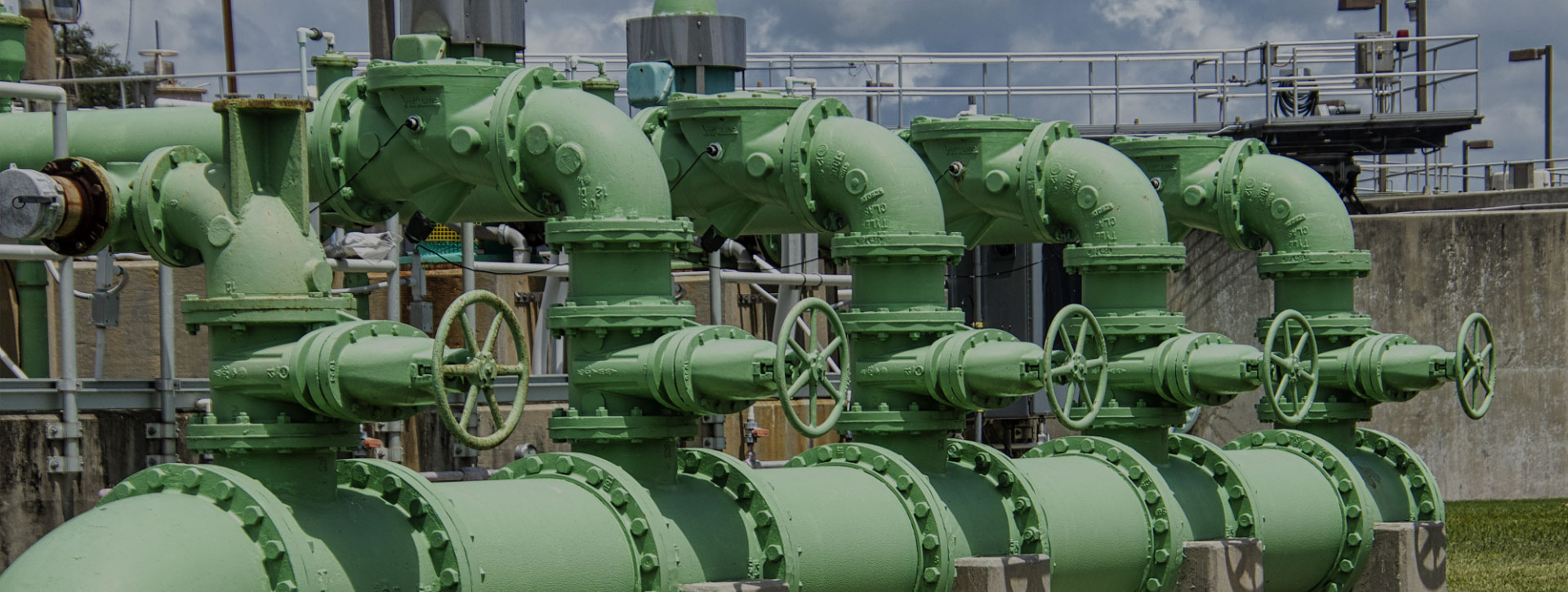
Serial floating ball valves are mainly applied to natural gas,oil products,chemical engineering,metallurgy,city building,environment protection,pharmacy and food industries, among which the anti-sulphur series are used for long delivery pipes of natural gas that contains hydrogen sulphide medium,a lot of impurity and corrosive substances.
The main structure features include:
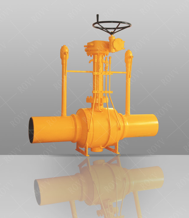
1.Construction of the shell
The valve bush of the stationary ball valve can be designed to three types:casting construction, forging construction, and full welding construction,according to user's demand or different working condition.And the ball valve of the full welding construction is mainly applied to underground operation.
2.The unique sealed structure of valve seat
Pre-ball sealed structure,post-ball sealed structure or pre-post-ball double sealed structures are available for choosing to different pressure,medium properties,and sealing requirements of the fixed ball valves.
3.Automatic pressure-relieving structure
When an abnormal rising of pressure appear in the hollow cavity,the single sealed-structure takes on the function of automatic pressure relieving,whiie the double-sealed structure can finish the job through a attached pressure-reliving device to the valve body.
4.Emergent repairman for the sealed structure
When leak was caused by damage on the valve seat or valve stick,the sealed grease injected through the grease feeding valve can seal the valve at once.
5.Fire-resistant Structure
According to the operating condition and user's requirement,ball valve can be designed with a fire-resistant structure up to the fire resistant standards of API607,API 6FA and JB/T6899.Once the soft seal ring is burnt out on fire,the structure can avoid serious leaking of the medium and prevent the fire from scaling up.
6.Anti-static Structure
While operating the valve,the friction between the sphere and the base will produce static charges accumulating on the sphere.To avoid static sparkle,the fire-resistant device is designed to derive the accumulated static sparkle,charges from the sphere.
7.Jam and release
When the valve is close,the valve seats will stop the effluence,and the precipitate in the can be released through the releasing device.
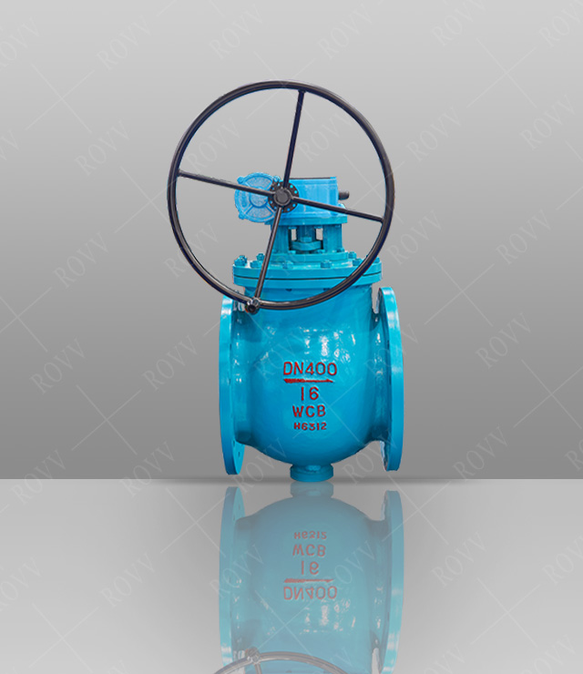
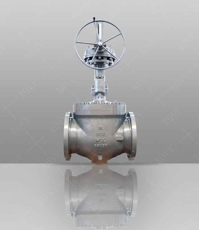
8.Locking Device
A locking structure is designed on the full-open and full-close spots of manual ball valves to avoid abnormal open-and-close produced by miss-operation or unpredictable circuit vibration.On production lines of petroleum and chemicals of flammable mediums,and during the course of outdoor piping,the design is especially advantageous and practical.
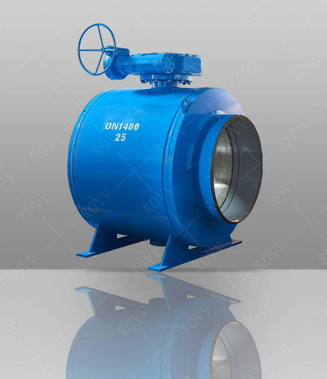
9.Full Drift Diameter Structure and Retractive Diameter Structure
The two structure series are produced to meet different requirement of users,The passage inside diameter of full diameter ball valves is the same as that of valve pipe,which is convenient for pipe cleaning.The weight of retractive diameter ball valves is relatively lighter,but the fluid resistance is just 1/7 that of stop valves with the same caliber.Therefore,the application prospects of retractive diameter series is much better.

Main overall dimensions PN1.6MPa CLASS 150
|
DN |
mm |
50 |
65 |
80 |
100 |
125 |
150 |
200 |
250 |
300 |
350 |
400 |
450 |
500 |
600 |
700 |
800 |
900 |
|
NPS |
in |
2 |
21/2 |
3 |
4 |
5 |
6 |
8 |
10 |
12 |
14 |
16 |
18 |
20 |
24 |
28 |
32 |
36 |
|
Flange |
L |
178 |
191 |
203 |
229 |
356 |
394 |
457 |
533 |
610 |
686 |
762 |
864 |
914 |
1067 |
1245 |
1372 |
1524 |
|
Butt welding |
L1 |
216 |
241 |
283 |
305 |
381 |
457 |
521 |
559 |
635 |
762 |
838 |
914 |
991 |
1143 |
1346 |
1524 |
1727 |
|
Manual |
H |
130 |
142 |
191 |
200 |
226 |
242 |
- |
- |
- |
- |
- |
- |
- |
- |
- |
- |
- |
|
W |
230 |
350 |
400 |
450 |
750 |
750 |
- |
- |
- |
- |
- |
- |
- |
- |
- |
- |
- |
|
|
WT(kg) |
12 |
28 |
33 |
50 |
78 |
93 |
- |
- |
- |
- |
- |
- |
- |
- |
- |
- |
- |
|
|
Gear |
H |
- |
- |
- |
- |
- |
- |
337 |
385 |
414 |
447 |
545 |
545 |
585 |
663 |
723 |
923 |
986 |
|
W |
- |
- |
- |
- |
- |
- |
600 |
600 |
800 |
800 |
800 |
800 |
800 |
800 |
800 |
800 |
800 |
|
|
WT(kg) |
- |
- |
- |
- |
- |
- |
250 |
390 |
578 |
770 |
1100 |
1250 |
1800 |
2400 |
4500 |
6900 |
9700 |
|
|
Pneumatic |
H |
269 |
379 |
389 |
479 |
552 |
666 |
769 |
824 |
897 |
937 |
1121 |
1161 |
1203 |
1145 |
1160 |
1460 |
1510 |
|
H1 |
174 |
248 |
258 |
322 |
395 |
457 |
560 |
615 |
653 |
691 |
816 |
856 |
898 |
915 |
930 |
1100 |
1150 |
|
|
L1 |
89 |
148 |
148 |
287 |
287 |
378 |
378 |
378 |
530 |
530 |
680 |
680 |
680 |
1455 |
1455 |
1665 |
1665 |
|
|
L2 |
181 |
257 |
257 |
287 |
287 |
378 |
378 |
378 |
530 |
530 |
680 |
680 |
680 |
1455 |
1455 |
1665 |
1665 |
|
|
WT(kg) |
32 |
42 |
53 |
100 |
125 |
157 |
265 |
410 |
595 |
795 |
1150 |
1295 |
1910 |
2400 |
4600 |
7100 |
10100 |
|
|
Eectric |
H |
- |
- |
- |
- |
- |
559 |
710 |
744 |
851 |
859 |
959 |
999 |
965 |
1141 |
1233 |
1341 |
1666 |
|
H1 |
- |
- |
- |
- |
- |
342 |
492 |
527 |
570 |
608 |
708 |
748 |
790 |
866 |
960 |
1068 |
1100 |
|
|
W |
- |
- |
- |
- |
- |
200 |
200 |
200 |
280 |
280 |
280 |
305 |
305 |
305 |
400 |
400 |
460 |
|
|
WT(kg) |
- |
- |
- |
- |
- |
152 |
245 |
425 |
610 |
800 |
1180 |
1300 |
1200 |
2500 |
4710 |
7300 |
10200 |