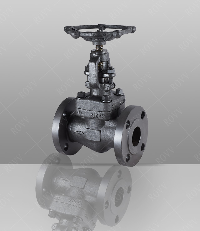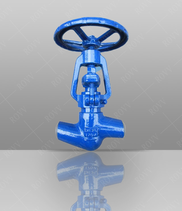
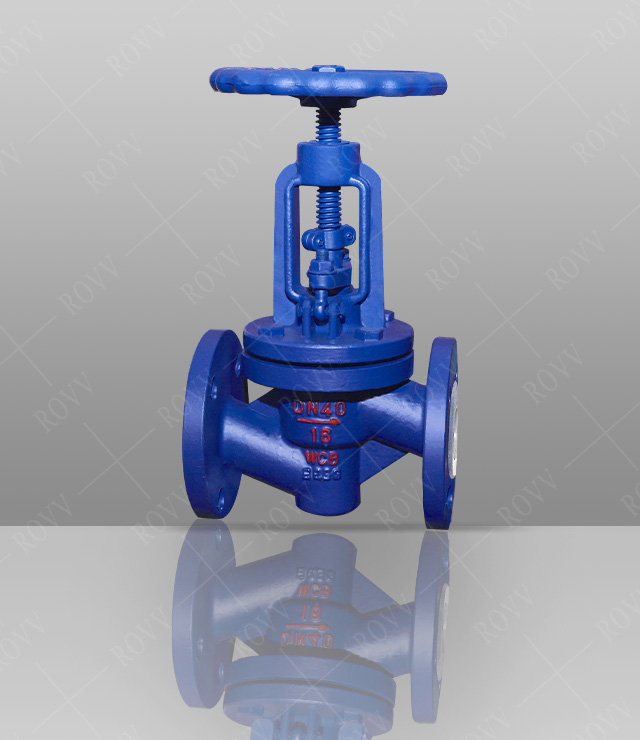
Fluorine lined globe valve
Technical Parameters
Product model: J41F46
Nominal diameter: DN15~350mm
Pressure range: PN1.0MPa~6.4MPa
Applicable temperature: -85℃~150℃
Design specification: GB/T12235-2007
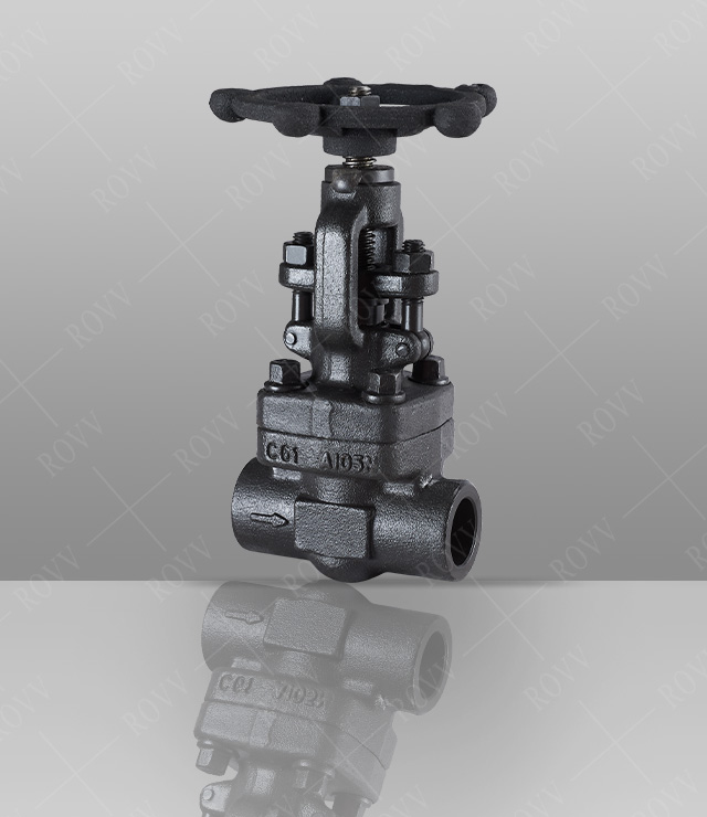
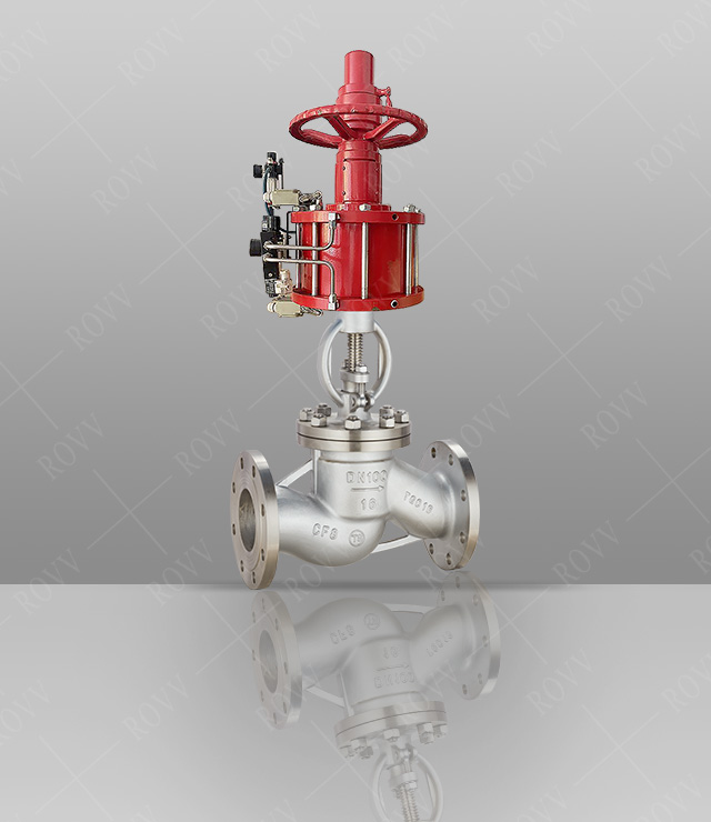
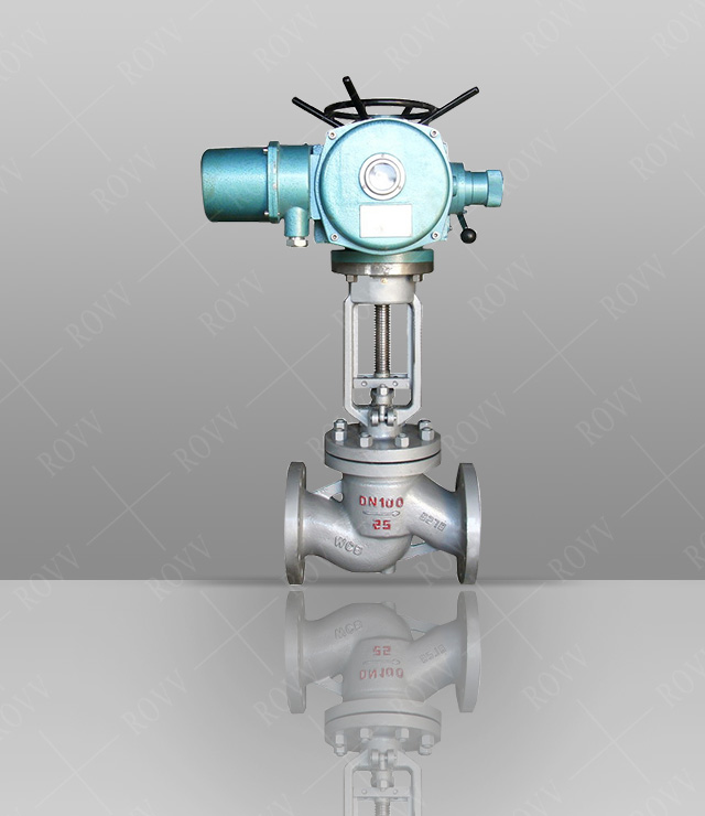
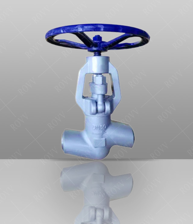
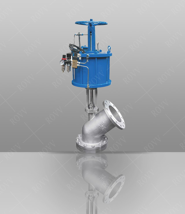
Drive mode: manual, pneumatic, electric
Lining Material: Polyperfluoroethylene FEP (F46)
Applicable media: solvents, reagents, acids, bases, ketones, aromatic hydrocarbons, chlorinated hydrocarbons
Product Description
The disc and stem of the flanged fluorine-lined globe valve are designed as an integral structure, and all the parts in contact with the internal parts and the medium are wrapped with fluorine, which has good anti-corrosion performance. It has the advantages of compact structure, flexible opening and closing, and short stroke. It is widely used in corrosive media or as a cut-off medium in pipeline systems such as petroleum and chemical industry. The fluorine-lined globe valve is strictly prohibited for flow adjustment, so as to avoid the high-speed medium flow generated at the orifice from eroding and destroying the sealing surface.
Product Features
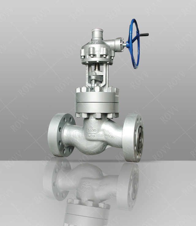
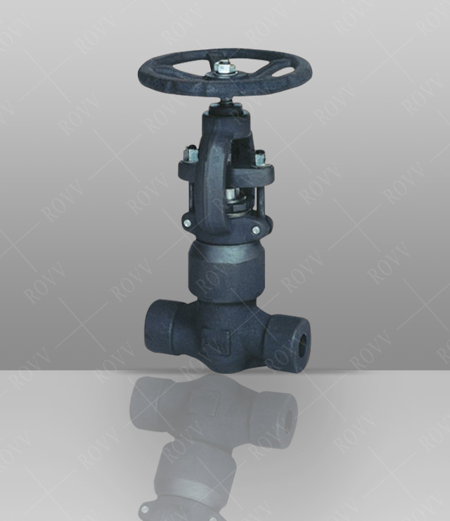
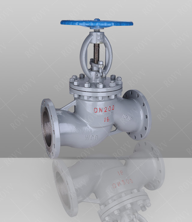
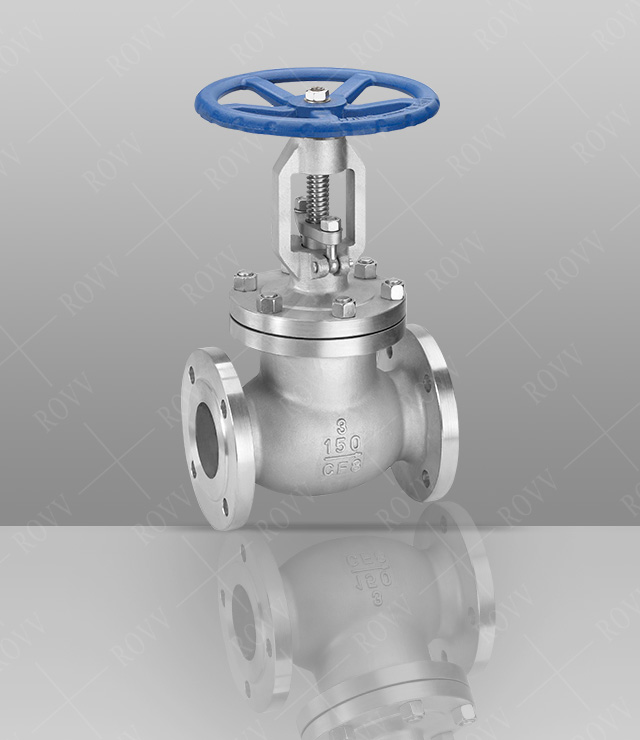
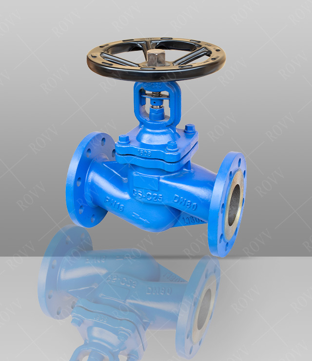
1. The structure of the flanged fluorine-lined globe valve is relatively simple, and the manufacture and maintenance are more convenient. When opening and closing, the valve flap stroke is small, the opening and closing time is short, and the valve height is small. The valve disc and the valve stem are designed as one structure, which is compact and safe to use.
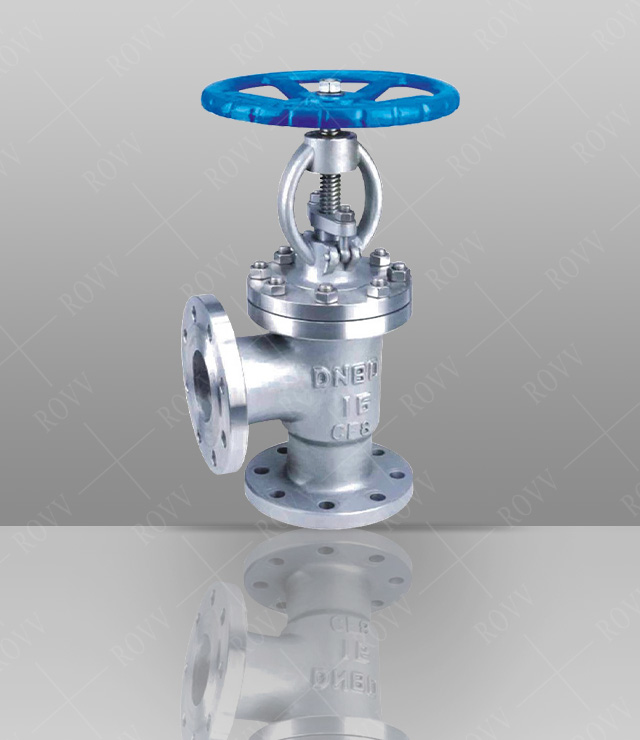
2. There are three structural forms of flanged fluorine-lined globe valve. Straight-through type, direct-flow type, and angle type, among which the straight-through type is commonly used, and the angle type can be installed at the corner of the pipeline system. The direct-flow type has the smallest flow resistance among globe valves.
3. Pneumatic and electric devices can be configured according to user needs to meet the needs of remote control and program control. Replacement parts lining material can be applied to a variety of media.
Main performance specifications
| Lining, valve seat | proper temperature(℃) | Applicable media |
| PTFE(F4) | ≤180 | Strong corrosive media such as various concentrations of acids, alkalis, salts, aqua regia, organic acids, etc., except molten alkali metals and elemental fluorine |
| PCTFE(F3) | ≤120 | |
| FEP(F46) | ≤150 | |
| PFA(fusibilityF4) | ≤180 | |
| PVDF(F2) | ≤100 | |
| RPTFE(RF4) | ≤180 |
Main parts material list
|
NO |
Part Name |
Grey cast iron |
Cast steel |
Stainless steel |
Ultra low carbon stainless steel |
||
|
Z |
C |
P |
R |
PL |
RL |
||
|
1 |
Body, bonnet |
HT250 |
WCB |
CF8 |
CF8M |
CF3 |
CF3M |
|
2 |
Disc, stem |
35 |
1Cr13 |
1Cr18NI9 |
1Cr18Ni12Mo2Ti |
00Cr18Ni10 |
00Cr17Ni14Mo2 |
|
3 |
Joint bolt |
35 |
35 |
1Cr17Ni2 |
1Cr17Ni2 |
1Cr17Ni2 |
1Cr17Ni2 |
|
4 |
Liner/Seat |
Lining hard rubber (NR) FEP (F46) PCTFE (F3) PFA (soluble polytetrafluoroethylene) |
|||||
|
5 |
Packing |
PTFE(F4) PTFE(F4) |
|||||
|
6 |
Packing gland |
WCB |
WCB |
CF8 |
CF8M |
CF3 |
CF3M |
|
7 |
Stem Nut |
ZCuAl10Fe3 ZCuAl10Fe3 |
|||||
|
8 |
Bolt |
35 |
35 |
1Cr17Ni2 |
1Cr17Ni2 |
1Cr17Ni9Ti |
1Cr17Ni9Ti |
|
9 |
Nut |
45 |
45 |
0Cr18Ni9 |
0Cr18Ni9 |
0Cr18Ni9 |
0Cr18Ni9 |
|
10 |
Handwheel |
HT200 |
HT200 |
WCC |
WCC |
WCC |
WCC |
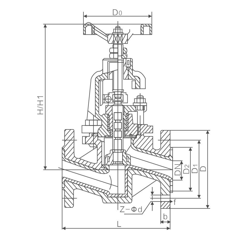
Main external connection dimensions
| DN | L | D | D1 | D2 | b | f | H | H1 | D0 | Z-φd |
| 15 | 130 | 95 | 65 | 45 | 16 | 2 | 240 | 265 | 100 | 4-φ14 |
| 20 | 150 | 105 | 75 | 58 | 18 | 2 | 240 | 265 | 100 | 4-φ14 |
| 25 | 160 | 115 | 85 | 68 | 18 | 2 | 240 | 265 | 120 | 4-φ14 |
| 32 | 180 | 140 | 100 | 78 | 18 | 2 | 260 | 290 | 140 | 4-φ18 |
| 40 | 200 | 150 | 110 | 88 | 18 | 2 | 290 | 325 | 140 | 4-φ18 |
| 50 | 230 | 165 | 125 | 102 | 18 | 2 | 300 | 335 | 160 | 4-φ18 |
| 65 | 290 | 185 | 145 | 122 | 18 | 2 | 355 | 400 | 180 | 8-φ18 |
| 80 | 310 | 200 | 160 | 138 | 20 | 2 | 400 | 450 | 240 | 8-φ18 |
| 100 | 350 | 220 | 180 | 158 | 20 | 2 | 495 | 455 | 240 | 8-φ18 |
| 125 | 400 | 250 | 210 | 188 | 22 | 2 | 530 | 560 | 280 | 8-φ18 |
| 150 | 480 | 285 | 240 | 212 | 22 | 2 | 650 | 605 | 320 | 8-φ22 |
| 200 | 600 | 340 | 295 | 268 | 24 | 2 | 650 | 770 | 360 | 12-φ22 |
| 250 | 730 | 405 | 355 | 320 | 26 | 2 | 690 | 810 | 400 | 12-φ26 |