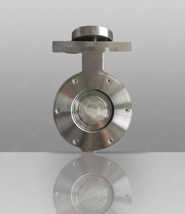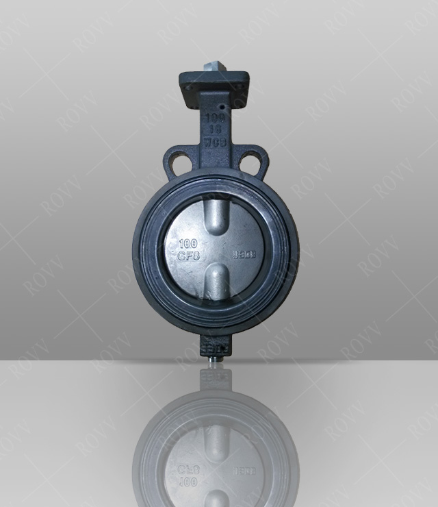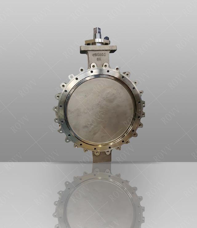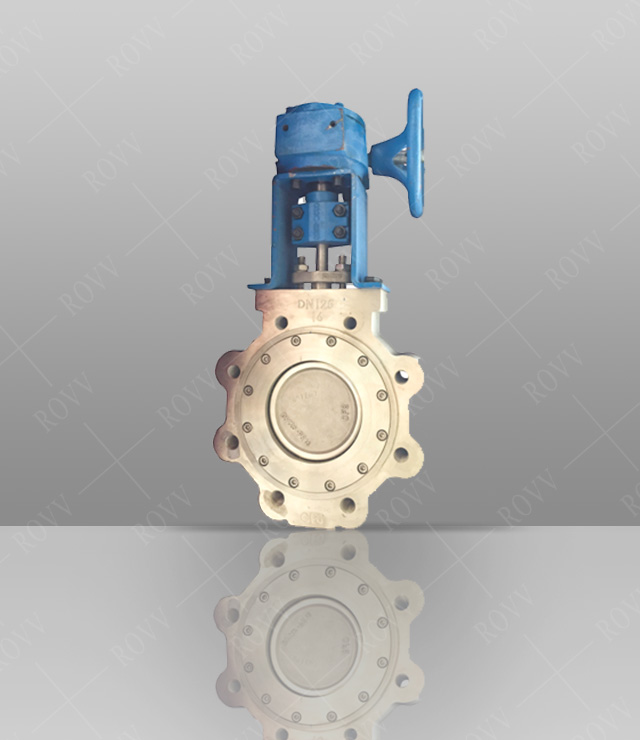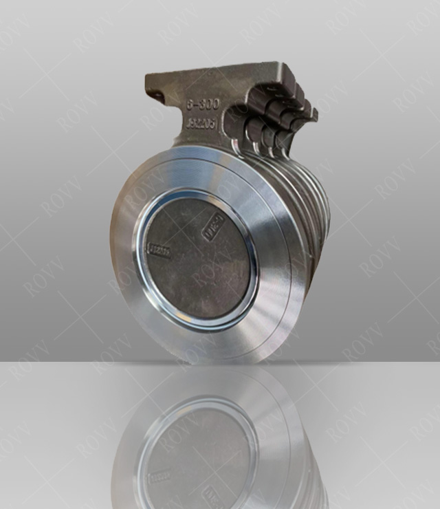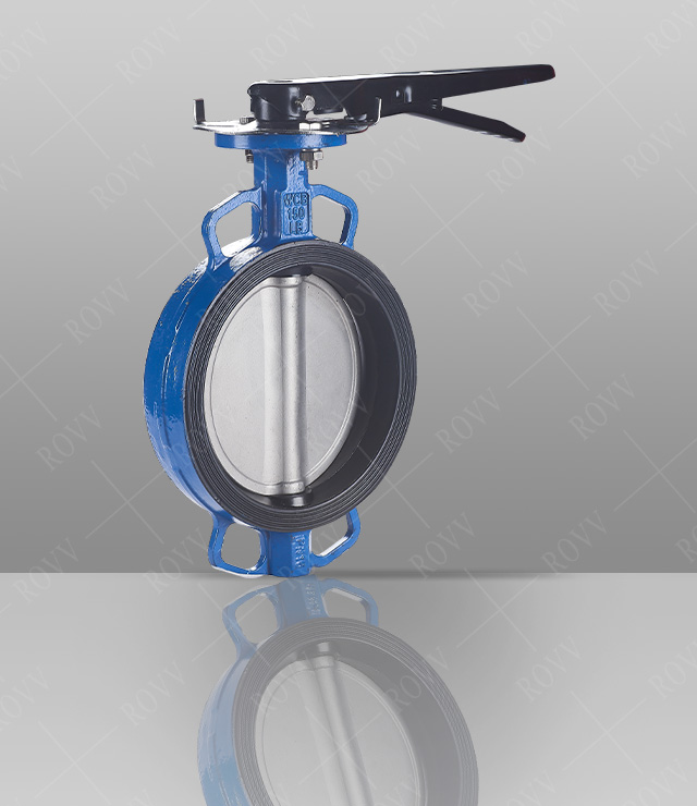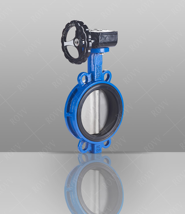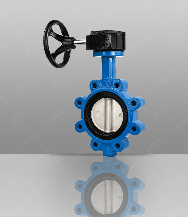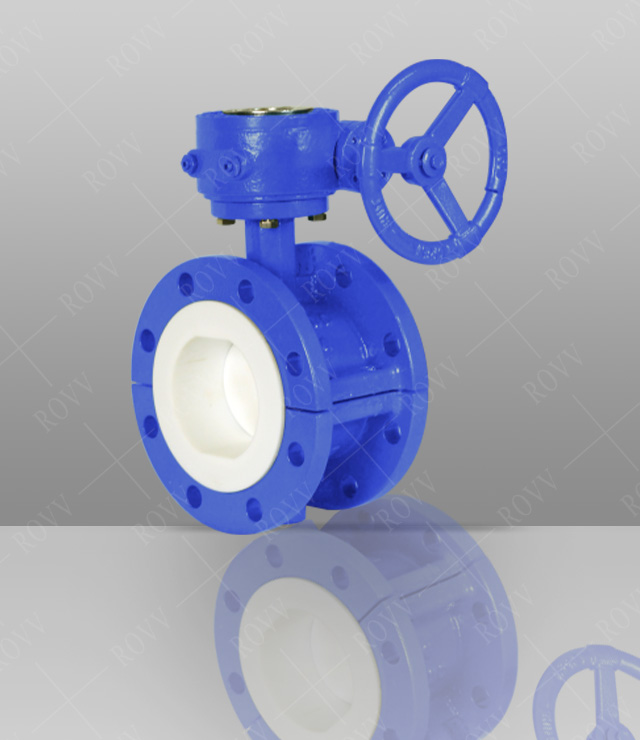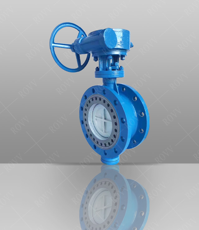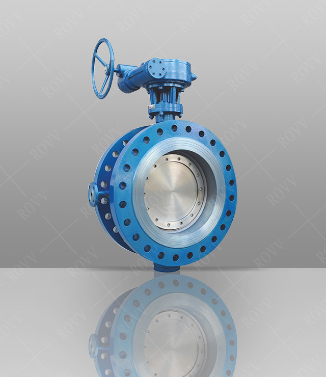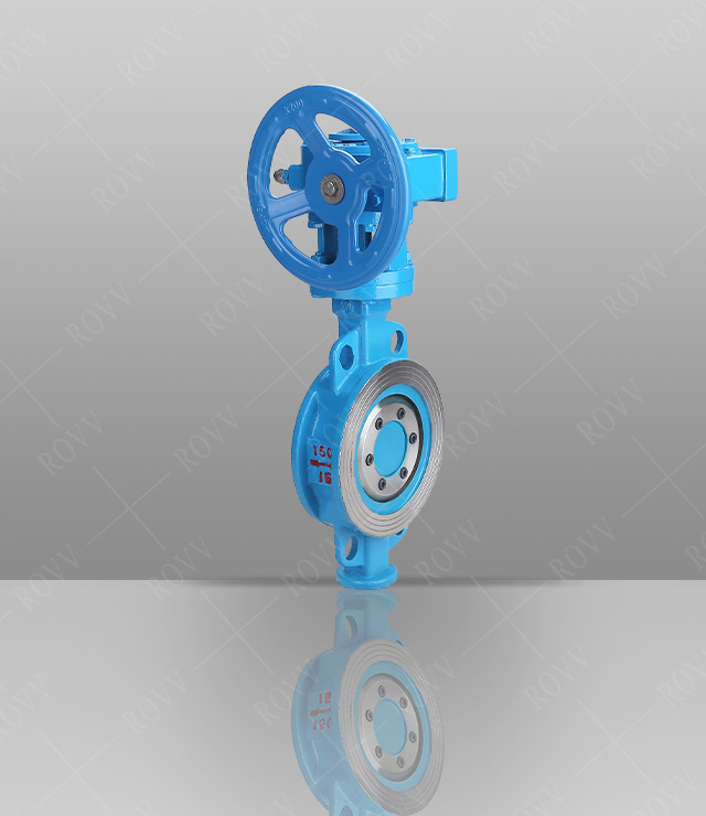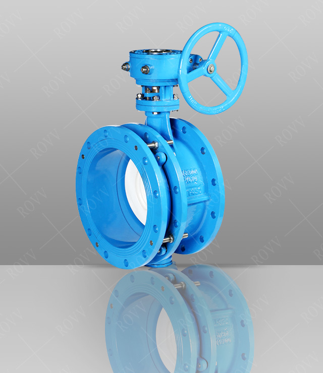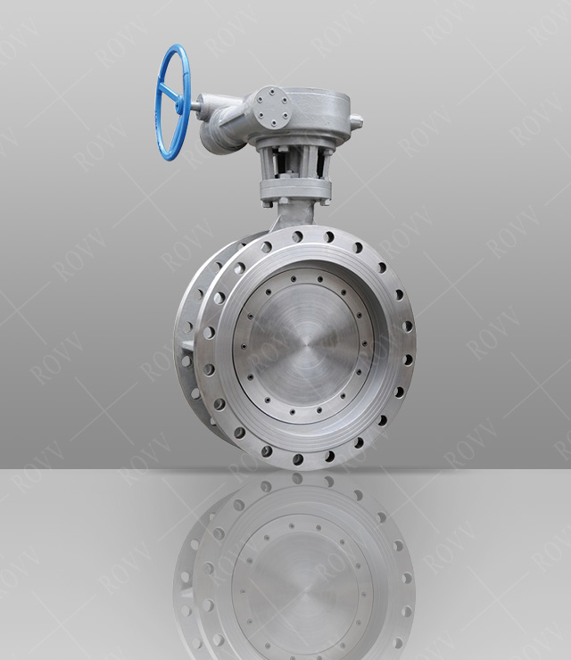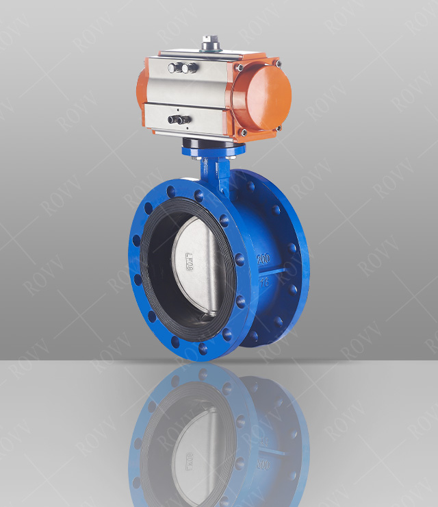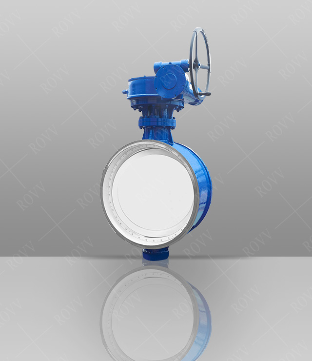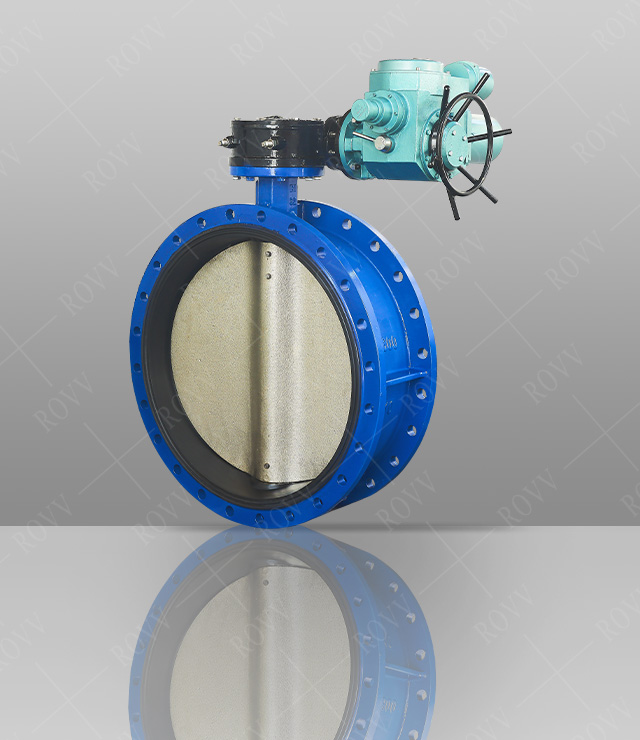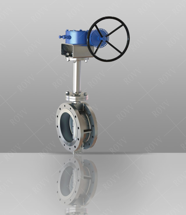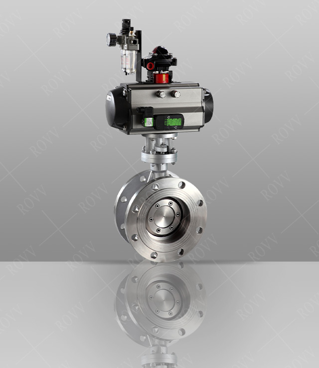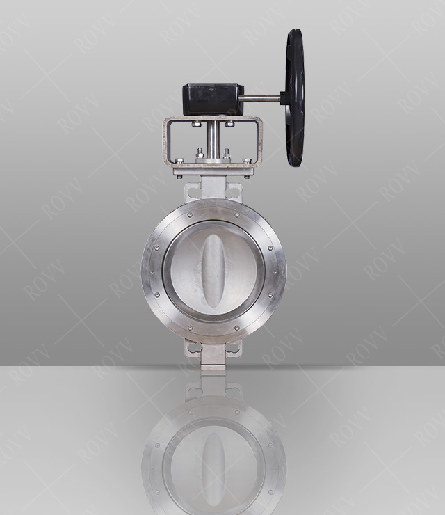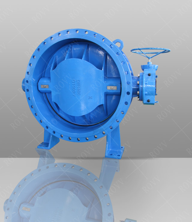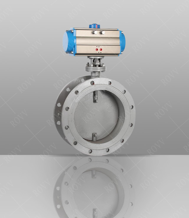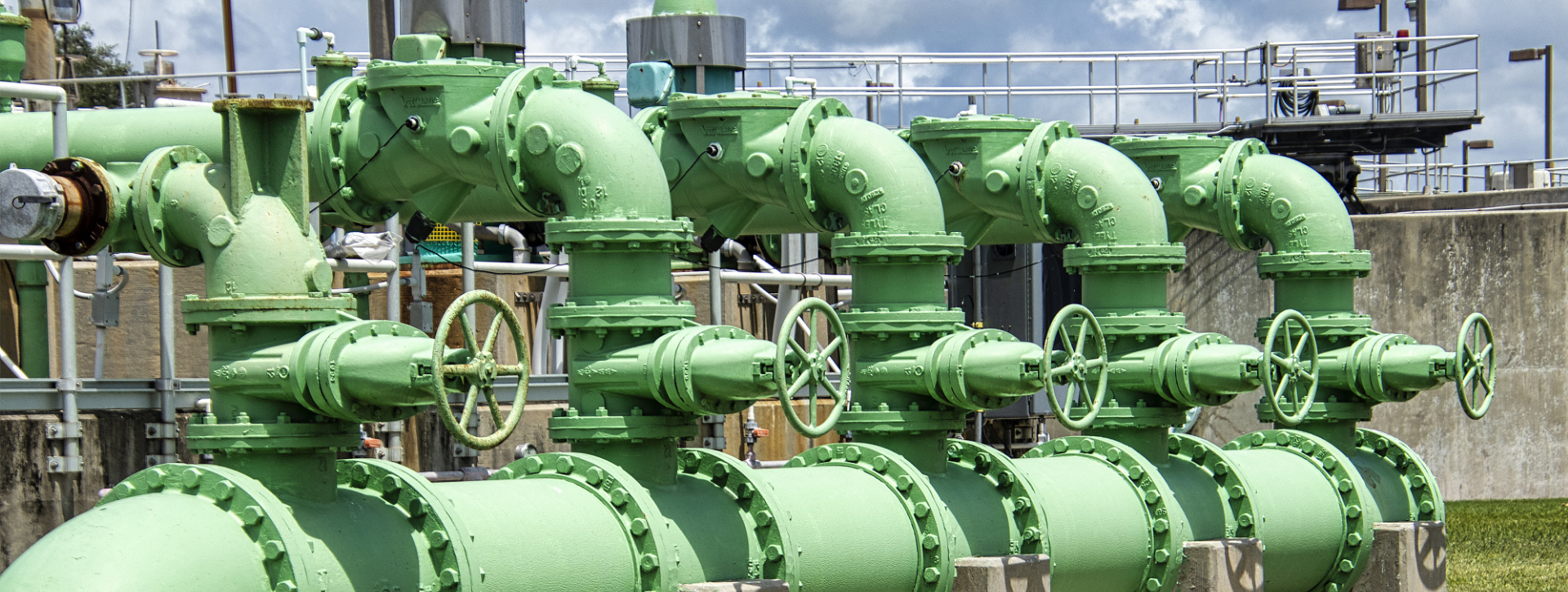
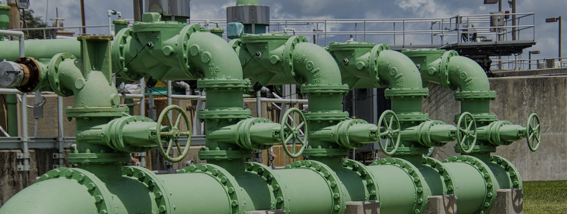
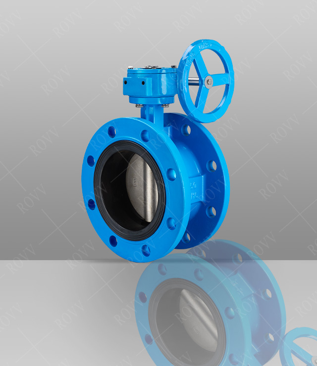
Flange Center Plate Butterfly Valve (Worm Gear)
Service Hotline: +86-21-33758111
Product Details
Technical Parameters
Product model: D341XNominal pressure: PN1.0~1.6MPa
Nominal diameter: DN50~DN1400
Connection method: flange
Medium used: water, oil, gas, and various corrosive media
Applicable temperature: -10~150 ℃
Connection standard: GB · ANSI · DIN · API · ISO · BS
Valve body material: cast iron; Ductile iron
Valve seat material: rubber
Valve plate material: stainless steel; Ductile iron
Technical Standard
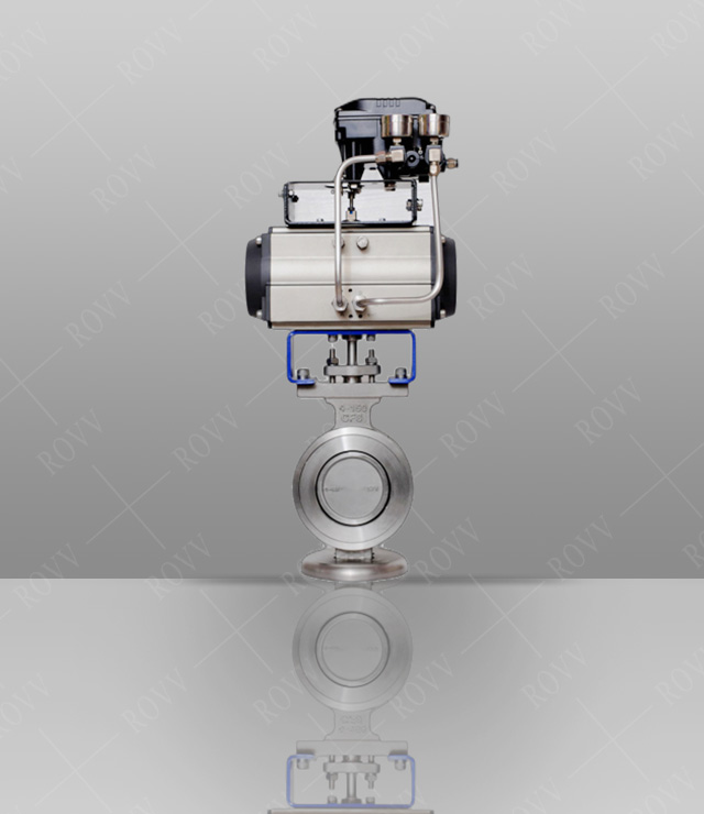
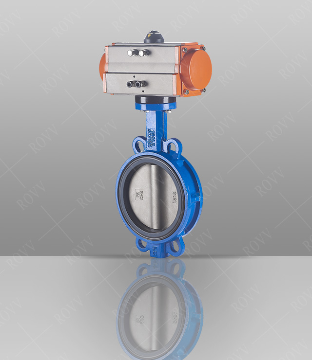
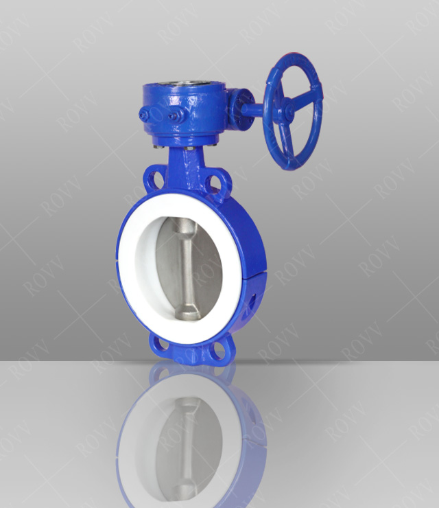
1.Device for regulating or cutting off medium in pipeline.2.Suitable for handle control device (DN50~300), worm gear, electric and pneumatic control device.
3.Design and manufacturing standards in line with GB/T12238.
4.Pressure test conforms to GB/T13927.
5.Structure length is GB/T12221.
6.Side flange standard conforms to GB/T17241.6.
Product Features
1.Can be equipped with a handle, worm gear, electric or pneumatic control device.2.Reduce the rotational torque, support the stem, and make it separate from the valve body effectively, reduce the wear of the valve stem.
3.After polishing treatment, with the valve seat precision.
4.To achieve zero leakage requirements of air tightness test. The opening and closing torque is small, prolong the service life of the valve seat.
5.Stem seal is not easy to deform, thereby avoiding the usual stem leakage.
6.The utility model has the advantages of high precision and high strength, and is suitable for the installation of the handle and other control devices.
7.The utility model is characterized in that the valve rod and the valve plate are firmly connected with the valve plate, and the utility model has the characteristics of anti vibration and easy replacement.
8.High precision, high reliability, easy to control the opening and closing of the valve plate.
9.Good overall stability, stable, tensile, anti leakage.
10.Auxiliary shaft end leakage.
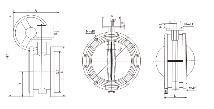
Main overall connection dimensions(PN1.0/1.6MPa)
| DN | L | D | D1 | D2 | b | f | N-d0 | A | K | E | F | H | H1 | H2 | Φ2 | N-d1 |
| 50 | 108 | 165 | 125 | 102 | 18 | 3 | 4-Φ18 | 180 | 65 | 50 | 13 | 83 | 338 | 28 | 12.6 | 4-Φ7 |
| 65 | 112 | 185 | 145 | 122 | 18 | 3 | 8-Φ18 | 180 | 65 | 50 | 13 | 93 | 358 | 28 | 12.6 | 4-Φ7 |
| 80 | 114 | 200 | 160 | 138 | 20 | 3 | 8-Φ18 | 245 | 65 | 50 | 13 | 100 | 413 | 28 | 12.6 | 4-Φ7 |
| 100 | 127 | 220 | 180 | 158 | 20 | 3 | 8-Φ18 | 240 | 90 | 70 | 13 | 114 | 428 | 28 | 15.77 | 4-Φ10 |
| 125 | 140 | 250 | 210 | 188 | 22 | 3 | 8-Φ18 | 240 | 90 | 70 | 13 | 125 | 444 | 28 | 18.92 | 4-Φ10 |
| 150 | 140 | 285 | 240 | 212 | 22 | 3 | 8-Φ22 | 350 | 90 | 70 | 13 | 143 | 553 | 28 | 18.92 | 4-Φ10 |
| 200 | 152 | 340 | 295 | 268 | 24 | 3 | 12-Φ22 | 350 | 125 | 102 | 13 | 170 | 678 | 38 | 22.1 | 4-Φ12 |
| 250 | 165 | 405 | 355 | 320 | 26 | 3 | 12-Φ26 | 550 | 125 | 102 | 13 | 198 | 742 | 38 | 28.45 | 4-Φ12 |
| 300 | 178 | 460 | 410 | 378 | 28 | 4 | 12-Φ26 | 600 | 125 | 102 | 20 | 223 | 803 | 38 | 31.6 | 4-Φ12 |
| 350 | 190 | 520 | 470 | 438 | 30 | 4 | 16-Φ26 | 600 | 150 | 125 | 20 | 270 | 866 | 45 | 31.6 | 4-Φ14 |
| 400 | 216 | 580 | 525 | 490 | 32 | 4 | 16-Φ30 | 600 | 175 | 140 | 20 | 300 | 940 | 51 | 33.15 | 4-Φ18 |
| 450 | 222 | 640 | 585 | 550 | 40 | 4 | 20-Φ30 | 750 | 175 | 140 | 20 | 340 | 995 | 51 | 37.95 | 4-Φ18 |
| 500 | 229 | 715 | 650 | 610 | 44 | 4 | 20-Φ33 | 750 | 175 | 140 | 22 | 355 | 1058 | 57 | 41.12 | 4-Φ18 |
| 600 | 267 | 840 | 770 | 725 | 54 | 5 | 20-Φ36 | 750 | 210 | 165 | 30 | 410 | 1163 | 70 | 50.63 | 4-Φ22 |
| 700 | 292 | 910 | 840 | 795 | 40 | 5 | 24-Φ36 | 750 | 300 | 254 | 30 | 478 | 1283 | 66 | 63.35 | 8-Φ18 |
| 800 | 318 | 1025 | 950 | 900 | 42 | 5 | 24-Φ39 | 750 | 300 | 254 | 30 | 529 | 1398 | 66 | 63.35 | 8-Φ18 |
| 900 | 330 | 1125 | 1050 | 1000 | 44 | 5 | 28-Φ39 | 1250 | 300 | 254 | 34 | 584 | 1498 | 118 | 75 | 8-Φ18 |
| 1000 | 410 | 1255 | 1170 | 1115 | 46 | 5 | 28-Φ42 | 1500 | 300 | 254 | 34 | 357 | 1608 | 142 | 85 | 8-Φ18 |
| 1200 | 470 | 1485 | 1390 | 1330 | 52 | 5 | 32-Φ48 | 1500 | 350 | 298 | 34 | 799 | 1876 | 150 | 105 | 8-Φ22 |